#include <cstdlib>
#include <iostream>
#include <sstream>
#include <string>
#include <RF24/RF24.h>
using namespace std;
//
// Hardware configuration
//
// CE Pin, CSN Pin, SPI Speed
// Setup for GPIO 22 CE and CE1 CSN with SPI Speed @ 4Mhz
//RF24 radio(RPI_V2_GPIO_P1_22, BCM2835_SPI_CS1,
BCM2835_SPI_SPEED_4MHZ);
// Setup for GPIO 22 CE and CE0 CSN with SPI Speed @ 4Mhz
RF24 radio(RPI_V2_GPIO_P1_22, BCM2835_SPI_CS0,
BCM2835_SPI_SPEED_4MHZ);
// Setup for GPIO 22 CE and CE0 CSN with SPI Speed @ 8Mhz
//RF24 radio(RPI_V2_GPIO_P1_22, BCM2835_SPI_CS0,
BCM2835_SPI_SPEED_8MHZ);
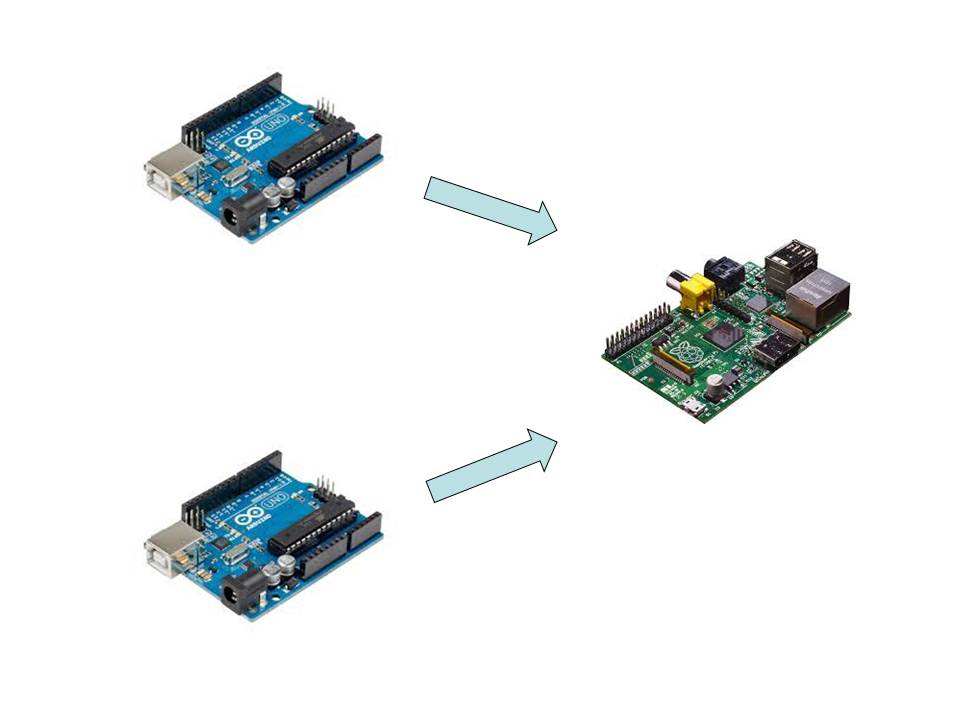
// Radio pipe addresses for the 2 nodes to communicate.
const uint8_t pipes[][6] =
{"1Node",
"2Node", "3Node"};
// {"1Node", "2Node",
"3Node", "4Node", "5Node", "6Node"};
int main(int argc, char** argv){
// Setup and configure rf radio
radio.begin();
radio.openWritingPipe(pipes[0]);
radio.openReadingPipe(1,pipes[1]);
radio.openReadingPipe(2,pipes[2]);
#if 0
radio.openReadingPipe(3,pipes[3]);
radio.openReadingPipe(4,pipes[4]);
radio.openReadingPipe(5,pipes[5]);
#endif
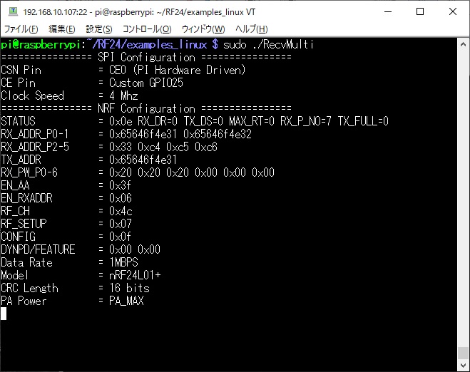
radio.startListening();
radio.printDetails();
// forever loop
uint8_t pipe;
while (1) {
// if there is data ready
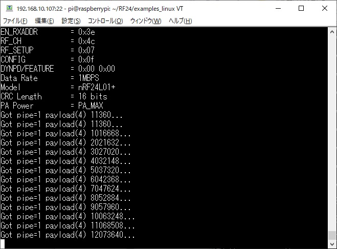
if (radio.available(&pipe)) {
// Dump the payloads until
we've gotten everything
unsigned long got_time;
// Fetch the payload.
radio.read(&got_time,
sizeof(unsigned long));
// Spew it
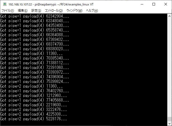
printf("Got pipe=%d
payload(%d) %lu...\n", pipe, sizeof(unsigned long),
got_time);
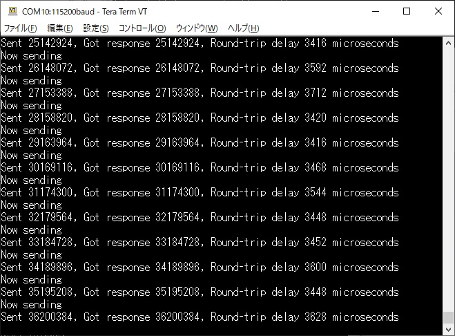
radio.stopListening();
radio.write(&got_time,
sizeof(unsigned long));
// Now, resume listening so
we catch the next packets.
radio.startListening();
delay(925); //Delay after
payload responded to, minimize RPi CPU time
}
} // end while
}
|