RaspberryとArduinoの無線通信

nRF24L01(その3)

こちらでArduinoとRaspberryの双方向通信を紹介しまし た。
1対1であれば、双方向通信を行うことができますが、1対nでは一方通行の通信となります。

nRF24L01の受信側はデータを受信すると自動的にACKを応答しますが、
この時、単純なACKではなく、Payload付きのACK(PayloadACK)を応答する機能が有ります。
PayloadACKの機能を使うことで1対nでも相手に応答を返す事ができます。

PayloadACKの機能を使う場合、writeAckPayload()という関数(メソッド)を使いますが、
RF24のクラスリファ レンスをよく読むと、writeAckPayload()の説明に

Write an ack payload for the specified pipe.
The next time a message is received on pipe, the data in buf will be sent back in the acknowledgement.

と書かれています。
要するに「次回メッセージを受信したときにACKとしてデータが返信される」ということで、
radio.read()の前にあらかじめ次のread時のACKを登録しておく必要があります。(こ このページが大いに参考になりました)

【Raspberry側】

Raspberry側のコード(RecvSimplePayloadAck.cpp)は以下の通りです。
受信しかしないのでWriteingPipeは使いません。
赤字の部分がPayloadACKに関するコードです。
#include <cstdlib>
#include <iostream>
#include <sstream>
#include <string>
#include <RF24/RF24.h>


using namespace std;
//
// Hardware configuration
//

// CE Pin, CSN Pin, SPI Speed

// Setup for GPIO 22 CE and CE1 CSN with SPI Speed @ 4Mhz
//RF24 radio(RPI_V2_GPIO_P1_22, BCM2835_SPI_CS1, BCM2835_SPI_SPEED_4MHZ);

// Setup for GPIO 22 CE and CE0 CSN with SPI Speed @ 4Mhz
RF24 radio(RPI_V2_GPIO_P1_22, BCM2835_SPI_CS0, BCM2835_SPI_SPEED_4MHZ);

// Setup for GPIO 22 CE and CE0 CSN with SPI Speed @ 8Mhz
//RF24 radio(RPI_V2_GPIO_P1_22, BCM2835_SPI_CS0, BCM2835_SPI_SPEED_8MHZ);

// Radio pipe addresses for the 2 nodes to communicate.
const uint8_t pipes[][6] = {"1Node"};

int main(int argc, char** argv){

  // Setup and configure rf radio
  radio.begin();

  // Enable Payload with Ack function
  radio.enableAckPayload(); // Enable dynamic payload on pipes 0 & 1
  radio.enableDynamicPayloads(); // Enable dynamic payload on all pipes

  radio.openReadingPipe(0,pipes[0]);
  radio.startListening();
  radio.printDetails();

  // forever loop
  unsigned long got_time;
  uint8_t pipe;
  static uint32_t message_count = 0;
  while (1) {
    if(radio.available(&pipe)){
      radio.writeAckPayload( pipe, &message_count, sizeof(message_count) );
      message_count++;

      radio.read(&got_time, sizeof(unsigned long));
      printf("pipe=%d payload=%lu\n",pipe, got_time);
    }
  } // end while
}

examples_linuxディレクトリにあるMakefileを修正してmakeします。
PROGRAMS = ...... RecvSimplePayloadAck

【Arduino側】

Arduino側のスケッチは以下の通りです。
赤字の部分がAutoAckに関するコードです。
/*
 * nRF24L01 Send Sample Program
 *
 * VCC  3.3V
 * MISO 12
 * MOSI 11
 * SCK  13
 * CE   7
 * CSN  8
 *
 */
#include <SPI.h>
#include "RF24.h"

// Set up nRF24L01 radio on SPI bus plus pins 7 & 8
RF24 radio(7, 8); // CE,CSN

// Radio pipe addresses for the 1 nodes to communicate.
byte addresses[][6] = {"SNode", "1Node"};


void setup(void)
{
  Serial.begin(115200);
  Serial.println("nTF24L01 Send Demo");
 
  radio.begin();

  // Enable Payload with Ack function
  radio.enableAckPayload();
 
  // Set the PA Level low to prevent power supply related issues.
  // RF24_PA_MAX is default.
  radio.setPALevel(RF24_PA_LOW);

  radio.openWritingPipe(addresses[1]);
  radio.openReadingPipe(1,addresses[0]);
  radio.stopListening();  // First, stop listening so we can talk.
}

void loop(void)
{
  // Take the time, and send it.  This will block until complete
  unsigned long start_time = micros();
  if (!radio.write( &start_time, sizeof(unsigned long) )){
    Serial.println(F("failed"));
  } else {
    Serial.print("start_time ");
    Serial.println(start_time);
    if ( radio.isAckPayloadAvailable() ) {
      uint32_t message_count;
      radio.read(&message_count,sizeof(message_count));
      Serial.print("Ack message_count=");
      Serial.println(message_count);
    }
  }
  delay(1000);
}

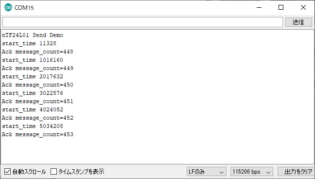
このスケッチをArduinoで実行すると、RaspberryからのPayload付きのAckデータを受け取ることができます。
Arduino(データ送信)→Raspberry(データ受信+PayloadAck応答)→Arduino(PayloadAck受信)とな ります。


さてArduinoが複数の場合は....

続く....