/* TS119 Address map
*
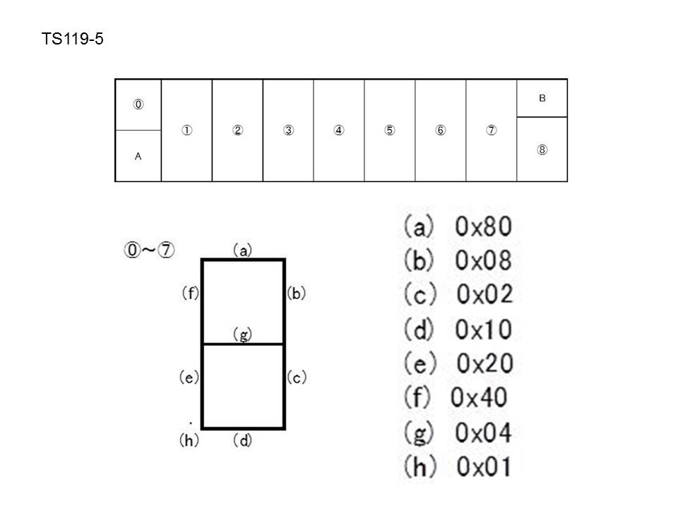
* +---+---+---+---+---+---+---+---+---+
* | 0 | 1 | 2 | 3 | 4 | 5 | 6 | 7
| |
* | | |
| | | |
| | 8 |
* +---+---+---+---+---+---+---+---+---+
*
* Address 0-7 is 8 segments
*
* a
* -
* f | | b
* - <-g
* e | | c
* h->. -
* d
*
* a = 0x80
* b = 0x08
* c = 0x02
* d = 0x10
* e = 0x20
* f = 0x40
* g = 0x04
* h = 0x01
*
*
*/
#include <stdio.h>
#include <stdint.h>
#include <wiringPi.h>
uint8_t _DATA_pin;
uint8_t _RW_pin;
uint8_t _CS_pin;
#define DATA 0
#define RW 1
#define CS 2
#define TAKE_CS() digitalWrite(_CS_pin,
LOW)
#define RELEASE_CS() digitalWrite(_CS_pin, HIGH)
uint8_t pattern[] = {
0xfa, // 0
0x0a, // 1
0xbc, // 2
0x9e, // 3
0x4e, // 4
0xd6, // 5
0xf6, // 6
0x8a, // 7
0xfe, // 8
0xde, // 9
0x04, // -
0x10, // _
0x6e, // H
0xf4, // E
0x70, // L
0xec, // P
0x00 // Space
};
enum Commands {
SYS_DIS = 0x00, /*!<
System disable. It stops the bias generator and the system
oscillator. */
SYS_EN = 0x02,
/*!< System enable. It starts the bias generator and
the system oscillator. */
LCD_OFF = 0x04, /*!<
Turn off the bias generator. */
LCD_ON = 0x06,
/*!< Turn on the bias generator. */
TIMER_DIS = 0x08, /*!< Disable time
base output. */
WDT_DIS = 0x0a, /*!<
Watch-dog timer disable. */
TIMER_EN = 0x0c, /*!< Enable
time base output. */
WDT_EN = 0x0e,
/*!< Watch-dog timer enable. The timer is reset. */
CLR_TIMER = 0x18, /*!< Clear the
contents of the time base generator. */
CLR_WDT = 0x1c, /*!<
Clear the contents of the watch-dog stage. */
TONE_OFF = 0x10, /*!< Stop
emitting the tone signal at the tone pin. \sa TONE2K,
TONE4K */
TONE_ON = 0x12, /*!<
Start emitting tone signal at the tone pin. Tone frequency
is selected using commands TONE2K or TONE4K. \sa TONE2K,
TONE4K */
TONE2K = 0xc0,
/*!< Output tone is at 2kHz. */
TONE4K = 0x80,
/*!< Output tone is at 4kHz. */
RC256K = 0x30,
/*!< System oscillator is the internal RC oscillator at
256kHz. */
XTAL32K = 0x50, /*!<
System oscillator is the crystal oscillator at 32768Hz. */
EXT256K = 0x38, /*!<
System oscillator is an external oscillator at 256kHz. */
//Set bias to 1/2 or 1/3 cycle
//Set to 2,3 or 4 connected COM lines
BIAS_HALF_2_COM = 0x40, /*!<
Use 1/2 bias and 2 commons. */
BIAS_HALF_3_COM = 0x48, /*!<
Use 1/2 bias and 3 commons. */
BIAS_HALF_4_COM = 0x50, /*!<
Use 1/2 bias and 4 commons. */
BIAS_THIRD_2_COM = 0x42, /*!< Use
1/3 bias and 2 commons. */
BIAS_THIRD_3_COM = 0x4a, /*!< Use
1/3 bias and 3 commons. */
BIAS_THIRD_4_COM = 0x52, /*!< Use
1/3 bias and 4 commons. */
IRQ_EN = 0x10,
/*!< Enables IRQ output. This needs to be excuted in
SPECIAL_MOD E. */
IRQ_DIS = 0x10, /*!<
Disables IRQ output. This needs to be excuted in
SPECIAL_MO DE. */
// WDT configuration commands
F1 = 0x80, /*!< Time base/WDT clock.
Output = 1Hz. Time-out = 4s. This needs to be excuted in
SPECIAL_MODE. */
F2 = 0x42, /*!< Time base/WDT clock.
Output = 2Hz. Time-out = 2s. This needs to be excuted in
SPECIAL_MODE. */
F4 = 0x44, /*!< Time base/WDT clock.
Output = 4Hz. Time-out = 1s. This needs to be excuted in
SPECIAL_MODE. */
F8 = 0x46, /*!< Time base/WDT clock.
Output = 8Hz. Time-out = .5s. This needs to be excuted in
SPECIAL_MODE. */
F16 = 0x48, /*!< Time base/WDT
clock. Output = 16Hz. Time-out = .25s. This needs to be
excuted in SPECIAL_MODE. */
F32 = 0x4a, /*!< Time base/WDT
clock. Output = 32Hz. Time-out = .125s. This needs to be
excuted in SPECIAL_MODE. */
F64 = 0x4c, /*!< Time base/WDT
clock. Output = 64Hz. Time-out = .0625s. This needs to be
excuted in SPECIAL_MODE. */
F128 = 0x4e, /*!< Time base/WDT
clock. Output = 128Hz. Time-out = .03125s. This needs to
be excuted in SPECIAL_MODE. */
//Don't use
TEST_ON = 0xc0, /*!<
Don't use! Only for manifacturers. This needs
SPECIAL_MODE. */
TEST_OFF = 0xc6, /*!< Don't
use! Only for manifacturers. This needs SPECIAL_MODE. */
COMMAND_MODE = 0x80, /*!< This is
used for sending standard commands. */
READ_MODE = 0xc0, /*!< This
instructs the HT1621 to prepare for reading the internal
RAM. */
WRITE_MODE = 0xa0, /*!< This
instructs the HT1621 to prepare for writing the internal
RAM. */
READ_MODIFY_WRITE_MODE = 0xa0, /*!<
This instructs the HT1621 to prepare for reading/modifying
batch of internal RAM adresses. */
SPECIAL_MODE = 0x90 /*!< This
instructs the HT1621 to prepare for executing a special
command. */
};
void HT1621_begin(uint8_t cs, uint8_t rw, uint8_t data)
{
_DATA_pin = data;
_RW_pin = rw;
_CS_pin = cs;
pinMode(_DATA_pin, OUTPUT);
pinMode(_RW_pin, OUTPUT);
pinMode(_CS_pin, OUTPUT);
digitalWrite(_CS_pin, HIGH);
digitalWrite(_RW_pin, HIGH);
digitalWrite(_DATA_pin, HIGH);
}
void HT1621_writeBits(uint8_t data, uint8_t cnt)
{
uint8_t i;
for(i=0;i<cnt;i++,data <<=1)
{
digitalWrite(_RW_pin, LOW);
delayMicroseconds(20);
digitalWrite(_DATA_pin, data&0x80 ? HIGH : LOW);
delayMicroseconds(20);
digitalWrite(_RW_pin, HIGH);
delayMicroseconds(20);
}
}
void HT1621_write(uint8_t address, uint8_t data)
{
TAKE_CS();
HT1621_writeBits(WRITE_MODE, 3);
HT1621_writeBits(address<<3, 6);
// 6 is because max address is 128
HT1621_writeBits(data, 8);
RELEASE_CS();
}
void HT1621_sendCommand(uint8_t cmd)
{
TAKE_CS();
HT1621_writeBits(COMMAND_MODE, 4);
HT1621_writeBits(cmd, 8);
RELEASE_CS();
}
void HT1621_init()
{
// HT1621_sendCommand(RC256K);
HT1621_sendCommand(BIAS_THIRD_4_COM);
HT1621_sendCommand(SYS_EN);
HT1621_sendCommand(LCD_ON);
}
void HT1621_clear(uint8_t places)
{
uint8_t i;
for (i = 0; i < places; i++)
HT1621_write(i, 0);
}
void HT1621_setNum(uint8_t adr, uint8_t num) {
HT1621_write(adr, pattern[num]);
}
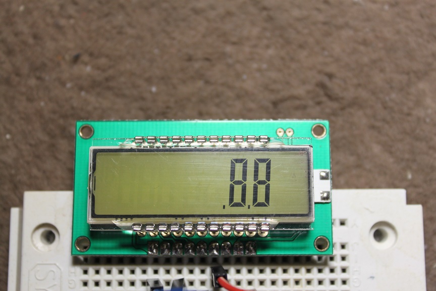
void HT1621_setDotNum(uint8_t adr, uint8_t num) {
HT1621_write(adr, pattern[num] | 0x01);
}
int main(int argc, char **argv) {
int i;
if(wiringPiSetup() == -1) {
printf("Setup Fail\n");
return 1;
}
HT1621_begin(CS,RW,DATA);
HT1621_init();
// clear memory
HT1621_clear(9);
for(i=0; i<6; i++) {
HT1621_clear(8);
HT1621_write(i, 0xff);
printf("address=%d\n",i);
getchar();
}
HT1621_clear(9);
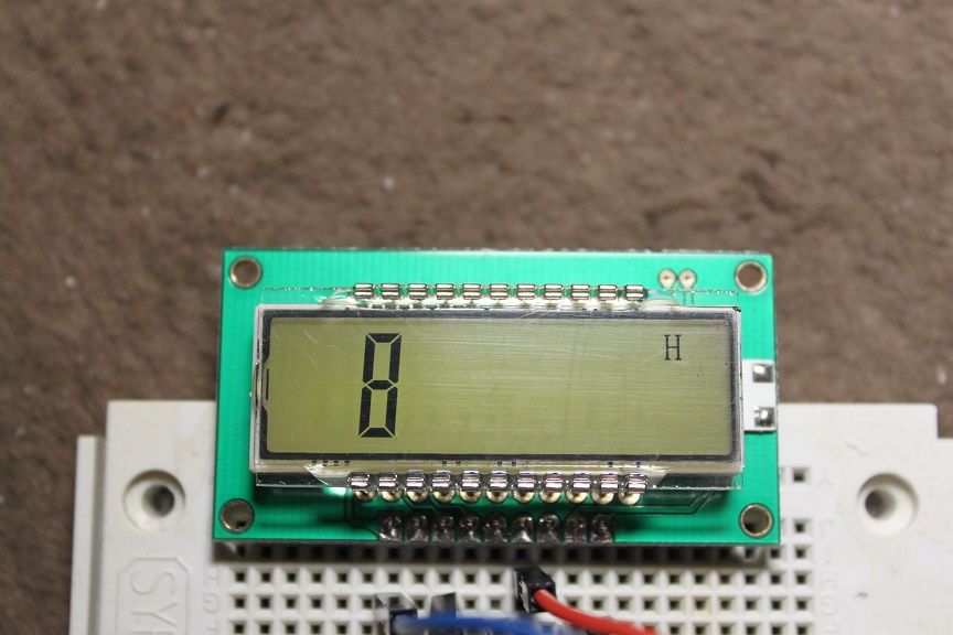
HT1621_write(6, 0xff);
HT1621_write(7, 0xff);
getchar();
HT1621_clear(9);
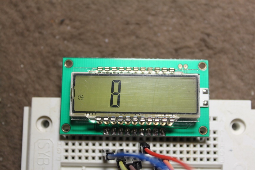
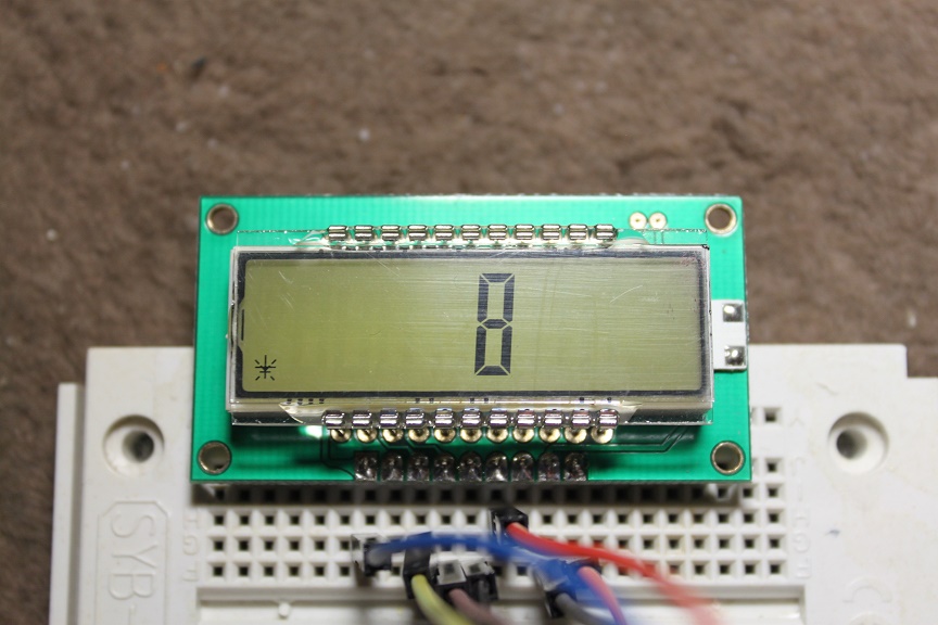
HT1621_write(8, 0xff);
getchar();
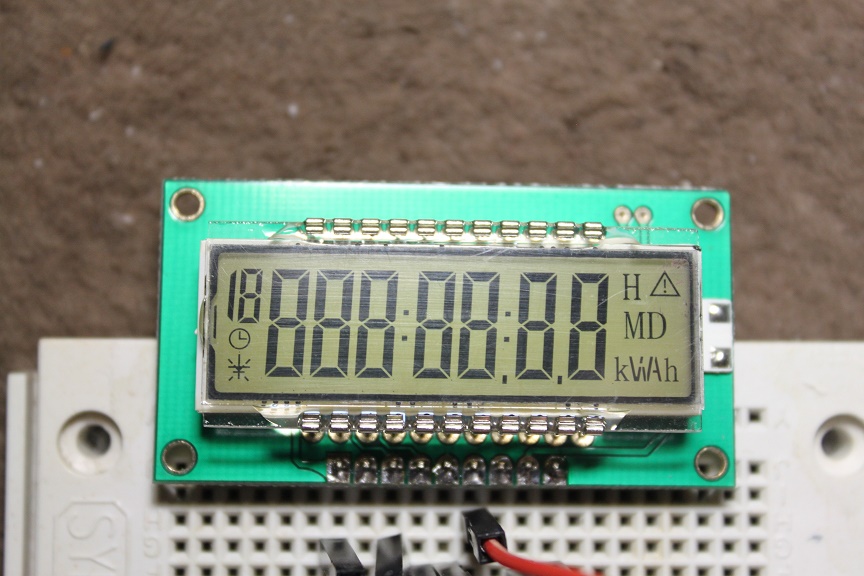
// all digit ON
HT1621_clear(9);
for(i=0; i<12; i++) {
HT1621_write(i, 0xff);
}
getchar();
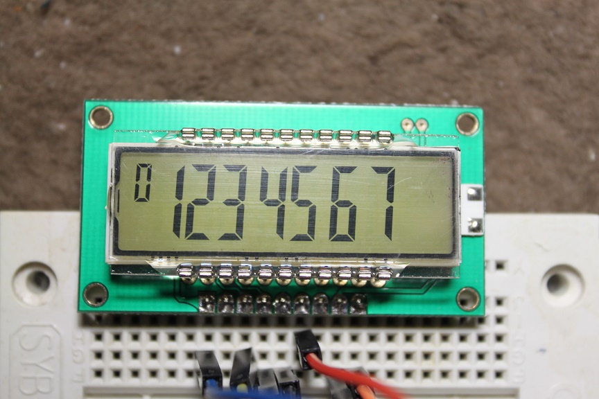
HT1621_clear(9);
HT1621_setNum(0,0);
HT1621_setNum(1,1);
HT1621_setNum(2,2);
HT1621_setNum(3,3);
HT1621_setNum(4,4);
HT1621_setNum(5,5);
HT1621_setNum(6,6);
HT1621_setNum(7,7);
getchar();
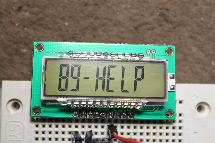
HT1621_setNum(0,16);
HT1621_setNum(1,8);
HT1621_setNum(2,9);
HT1621_setNum(3,10);
HT1621_setNum(4,12); // H
HT1621_setNum(5,13); // E
HT1621_setNum(6,14); // L
HT1621_setNum(7,15); // P
getchar();
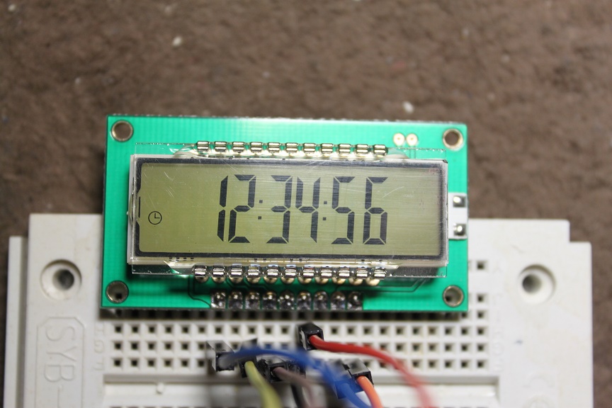
HT1621_setNum(0,16);
HT1621_setDotNum(1,16); // with colon
HT1621_setNum(2,1);
HT1621_setDotNum(3,2); // with clock mark
HT1621_setNum(4,3);
HT1621_setNum(5,4);
HT1621_setNum(6,5);
HT1621_setNum(7,6);
getchar();
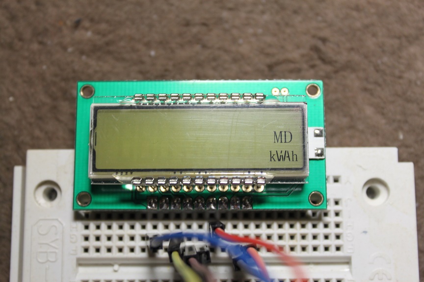
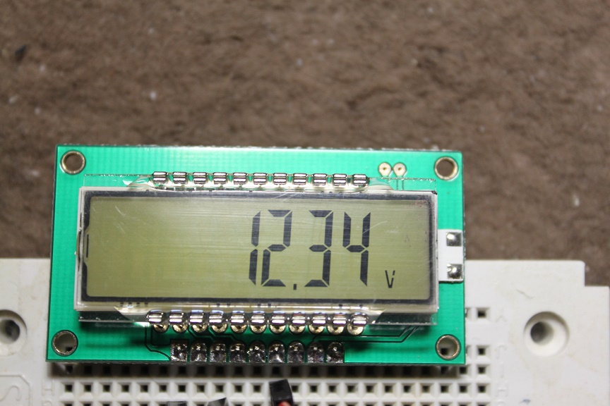
HT1621_setNum(0,16);
HT1621_setNum(1,16);
HT1621_setNum(2,16);
HT1621_setNum(3,16);
HT1621_setNum(4,1);
HT1621_setNum(5,2);
HT1621_setDotNum(6,3);
HT1621_setNum(7,4);
HT1621_write(8,0x0c); // V
getchar();
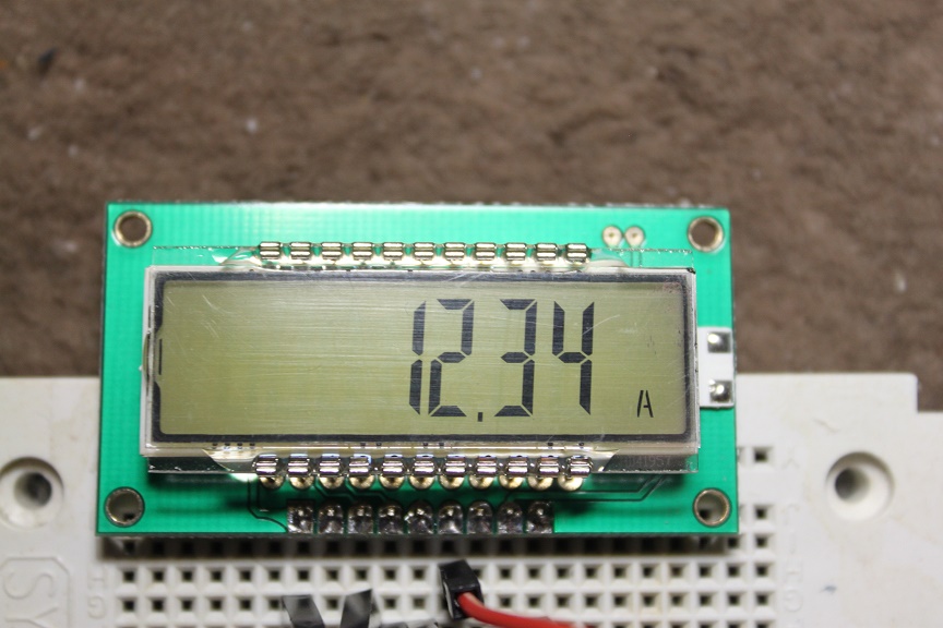
HT1621_write(8,0x11); // A
getchar();
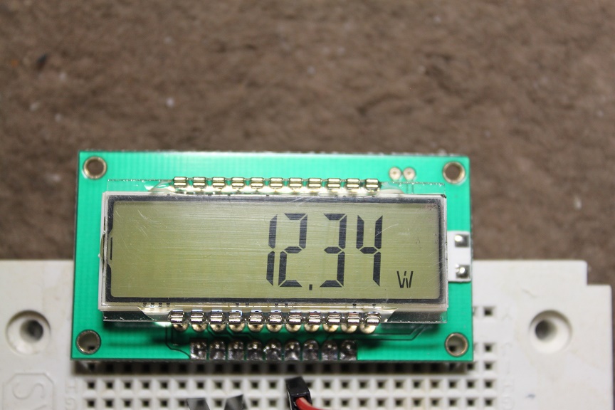
HT1621_write(8,0x0f); // W
getchar();
HT1621_clear(9);
}
|