#include <stdio.h>
#include <string.h>
#include <unistd.h>
#include <wiringPi.h>
#include <wiringPiI2C.h>
// MCP23017 registers (everything except direction
defaults to 0)
#define IODIRA 0x00 // IO
direction (0 = output, 1 = input (Default))
#define IODIRB 0x01
#define IPOLA 0x02 // IO
polarity (0 = normal, 1 = inverse)
#define IPOLB 0x03
#define GPINTENA 0x04 // Interrupt on change
(0 = disable, 1 = enable)
#define GPINTENB 0x05
#define DEFVALA 0x06 // Default
comparison for interrupt on change (interrupts on
opposite)
#define DEFVALB 0x07
#define INTCONA 0x08 // Interrupt
control (0 = interrupt on change from previous, 1 =
interrupt on change from DEFVAL)
#define INTCONB 0x09
#define IOCONA 0x0A // IO
Configuration:
bank/mirror/seqop/disslw/haen/odr/intpol/notimp
#define IOCONB 0x0B
#define GPPUA 0x0C //
Pull-up resistor (0 = disabled, 1 = enabled)
#define GPPUB 0x0D
#define INTFA 0x0E //
Interrupt flag (read only) : (0 = no interrupt, 1 = pin
caused interrupt)
#define INTFB 0x0F
#define INTCAPA 0x10 // Interrupt
capture (read only) : value of GPIO at time of last
interrupt
#define INTCAPB 0x11
#define GPIOA 0x12 // Port
value. Write to change, read to obtain value
#define GPIOB 0x13
#define OLLATA 0x14 // Output
latch. Write to latch output.
#define OLLATB 0x15
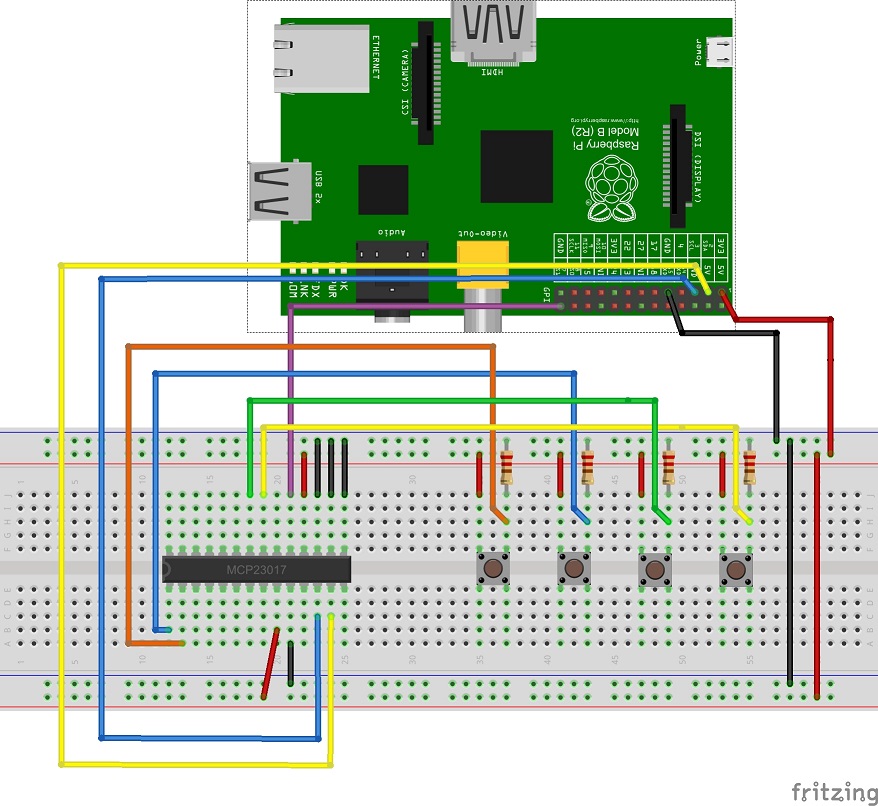
#define I2C_ADDR 0x20 // MCP23017 is on I2C
port 0x20
#define PIE_PIN 11 //
Raspberry Interrupt Pin Number
#define ON 0
#define OFF 1
int keyPressed;
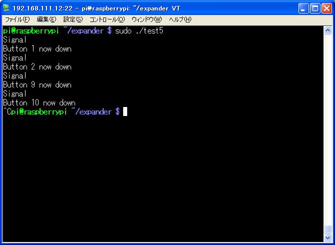
void signal(void){
printf("Signal\n");
keyPressed = ON;
}
void handleKeypress (int fd) {
unsigned int keyValue;
int ret,ret2;
int button;
delay (100); // de-bounce before
we re-enable interrupts
keyPressed = OFF; // ready for
next time through the interrupt service routine
// Read port values, as required. Note that this re-arms
the interrupts.
ret = wiringPiI2CReadReg8(fd,INTFA);
if (ret != 0) {
ret2 =
wiringPiI2CReadReg8(fd,INTCAPA);
keyValue =
ret; // read value at time of interrupt
}
ret = wiringPiI2CReadReg8(fd,INTFB);
if (ret != 0) {
ret2 =
wiringPiI2CReadReg8(fd,INTCAPB);
keyValue =
ret*256; // port B is in low-order byte
}
// display which buttons were down at the time of the
interrupt
for (button = 0; button < 16;
button++) {
// this key down?
if (keyValue
& (1 << button)) {
printf("Button %0d now down\n",button+1);
} // end
of if this bit changed
}
}
int main(void){
int fd,ret;
// I2C Setup
fd = wiringPiI2CSetup(I2C_ADDR);
if (fd == -1) {
printf("wiringPiI2CSetup Error\n");
return 1;
}
// GPIO Setup
if (wiringPiSetup() == -1) {
printf("wiringPiSetup Error\n");
return 1;
}
// expander configuration register
// mirror interrupts, disable sequential mode
if((wiringPiI2CWriteReg8(fd,IOCONA,0x60))<0){
printf("write
error register ICONA");
}
if((wiringPiI2CWriteReg8(fd,IOCONB,0x60))<0){
printf("write
error register ICONB");
}
// enable pull-up on switches
// pull-up resistor for switch - both ports
if((wiringPiI2CWriteReg8(fd,GPPUA,0xFF))<0){
printf("write
error register GPPUA");
}
if((wiringPiI2CWriteReg8(fd,GPPUB,0xFF))<0){
printf("write
error register GPPUB");
}
// invert polarity
// invert polarity of signal - both ports
if((wiringPiI2CWriteReg8(fd,IPOLA,0xFF))<0){
printf("write
error register IPOLA");
}
if((wiringPiI2CWriteReg8(fd,IPOLB,0xFF))<0){
printf("write
error register IPOLB");
}
// enable all interrupts
// enable interrupts - both ports
if((wiringPiI2CWriteReg8(fd,GPINTENA,0xFF))<0){
printf("write
error register GPINTENA");
}
if((wiringPiI2CWriteReg8(fd,GPINTENB,0xFF))<0){
printf("write
error register GPINTENB");
}
// read from interrupt capture ports to clear them
ret = wiringPiI2CReadReg8(fd,INTCAPA);
ret = wiringPiI2CReadReg8(fd,INTCAPB);
wiringPiISR( PIE_PIN, INT_EDGE_FALLING, signal );
keyPressed=OFF;
while(1){
sleep(1);
if (keyPressed
== ON) handleKeypress (fd);
}
return 0;
} |