$ cat /etc/os-release |
$ python3 --version |
$ vi $HOME/.profile |
$ pio lib --global install 2093 |
#include <Arduino.h> |
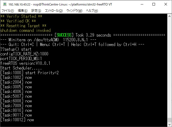
$ pio run -t upload -e nucleo_f446re
&& pio device monitor -b 115200 |
could not open port '/dev/ttyACM0':
              [Errno 13] could not open port /dev/ttyACM0: [Errno 13]
Permission denied: '/dev/ttyACM0' |
$ ls -l /dev/ttyACM0 |
xPack OpenOCD x86_64 Open On-Chip
Debugger 0.11.0+dev (2021-10-16-21:15) |
$ git clone
https://github.com/stlink-org/stlink |
; PlatformIO Project Configuration File |

$ lsusb |
$ ls -l /dev/stlinkv2* |
$ ls -l /dev/stlinkv2* |
$ ls /dev/st* |
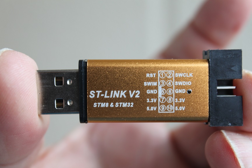
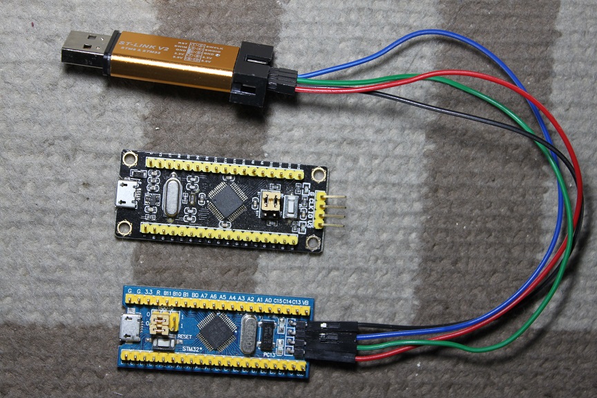
| ST-LINK | STM32 |
|---|---|
| 3.3V | 3.3V |
| GND | GND |
| SWDIO | SWIO(=PA13) |
| SWCLK | SWCLK(=PA14) |
$ cat platformio.ini |
$ pio run -t upload -e bluepill_f103c8
&& pio device monitor -b 115200 -p /dev/ttyUSB0 |
      +------------+


      +------------+


      +------------+

      | STM32 F103
      |
      |  ST-LINK
      |


      |    HOST    |

      |


      |


      |


      |


      |


      |

      |      PA13  +------------+
      SWIO
      |/dev/stlinkv2|


      |

      |      PA14  +------------+
      SWCLK
      +=============+


      |

      |      3.3V  +------------+
      3.3V
      |


      |


      |

      |      GND   +------------+ GND

      |


      |


      |

      |


      |


      |


      |


      |


      |

      |


      |


      +------------+


      |


      |

      |


      |


      |


      |

      |


      |


      +------------+


      |


      |

      |


      |


      |   USB-TTL
      |


      |


      |

      |            |
               |

      |


      |


      |

      |      PA9   +------------+
      RX         |/dev/ttyUSB0
      |
      |

      |      PA10  +------------+
      TX
      +=============+


      |

      |      GND   +------------+
      GND
      |


      |


      |

      |


      |


      |


      |


      |


      |

      +------------+


      +------------+


      +------------+
$ pio run -t upload -e bluepill_f103c8
|
      +------------+


      +------------+


      +------------+

      | STM32 F103
      |
      |  ST-LINK
      |


      |    HOST    |

      |


      |


      |


      |


      |


      |

      |      PA13  +------------+
      SWIO
      |/dev/stlinkv2|


      |

      |      PA14  +------------+
      SWCLK
      +=============+


      |

      |      3.3V  +------------+
      3.3V
      |


      |


      |

      |      GND   +------------+
      GND
      |


      |


      |

      |


      |


      |


      |


      |


      |

      |


      |


      +------------+


      +------------+

      |


      |


      |


      |


      +------------+


      +------------+

      |


      |


      |   USB-TTL
      |


      |  Windows   |

      |


      |


      |


      |


      |


      |

      |      PA9   +------------+
      RX         |/dev/ttyUSB0
      |
      |

      |      PA10  +------------+
      TX
      +=============+


      |

      |      GND   +------------+
      GND
      |


      |


      |

      |


      |


      |


      |


      |


      |

      +------------+


      +------------+


      +------------+
bluepill_f103c8の定義を使ってビルドした場合、以下の4つのシリアルオブジェクトを使うことができま す。| TX | RX | |
| Serial | PA9 | PA10 |
| Serial1 | PA9 | PA10 |
| Serial2 | PA2 | PA3 |
| Serial3 | PB10 | PB11 |
Configuring upload protocol... |
[env:genericSTM32F405RG] |
$ cat platformio.ini |
| TX | RX | |
| Serial | USB | USB |
| Serial1 | PA9 | PA10 |
| Serial2 | PA2 | PA3 |
| Serial3 | PB10 | PB11 |
$pio run -e bluepill_f103c8_usbcon -t
              upload && pio device monitor -b 115200 -p
/dev/ttyACM0 |
+------------+


      +------------+


      +------------+

      | STM32 F103
      |
      |  ST-LINK
      |


      |    HOST    |

      |


      |


      |


      |


      |


      |

      |       PA13 +------------+
      SWIO
      |/dev/stlinkv2|


      |

      |       PA14 +------------+
      SWCLK
      +=============+


      |

      |       GND  +------------+
      GND
      |


      |


      |

      |


      |


      |


      |


      |


      |

      |


      |


      +------------+


      |


      |

      |


      |


      |


      |

      |


      |


      /dev/ttyACM0
      |
      |

      |       USB
      +=======================================+


      |

      |


      |


      |


      |

      |


      |


      |


      |

      +------------+


      +------------+
その後の調査でBluePillやBlackPillはUSBポートから給電することができますが、USBポートから給電できるかどうかは、$ cd $HOME |
$ st-info --probe |
$ st-info --probe |
Found 1 stlink programmers |
$ pio run -e bluepill_f103c8 |