/*
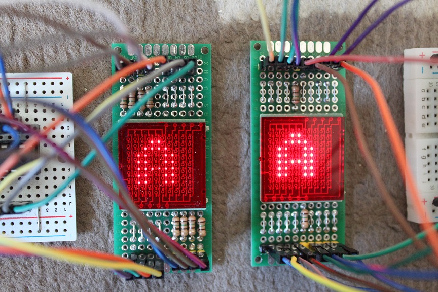
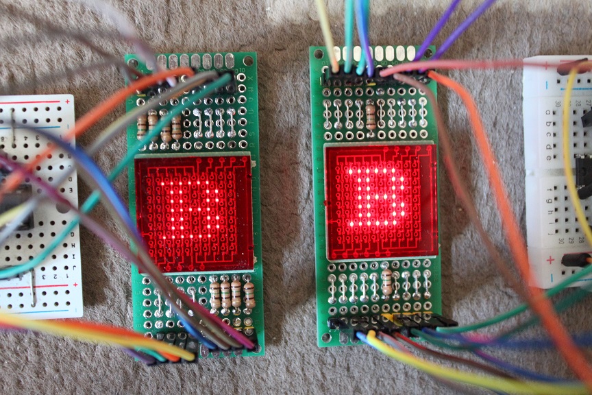
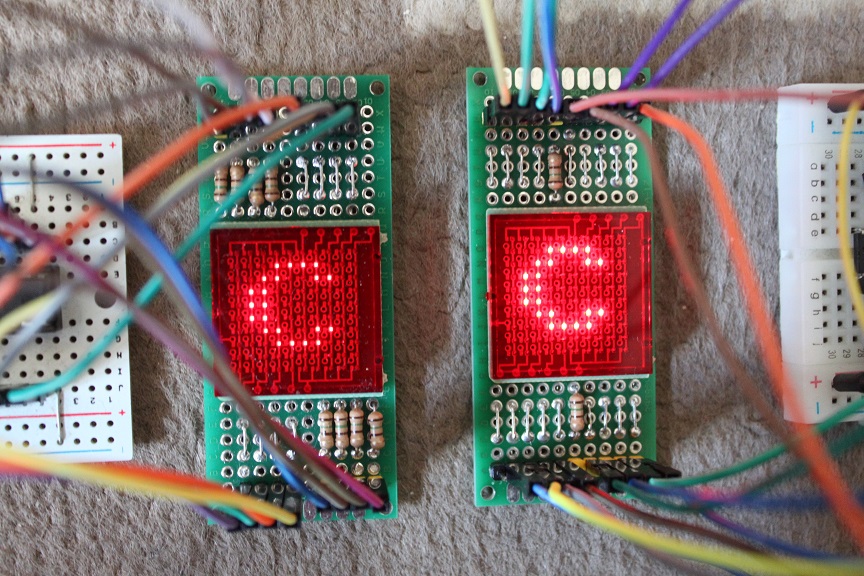
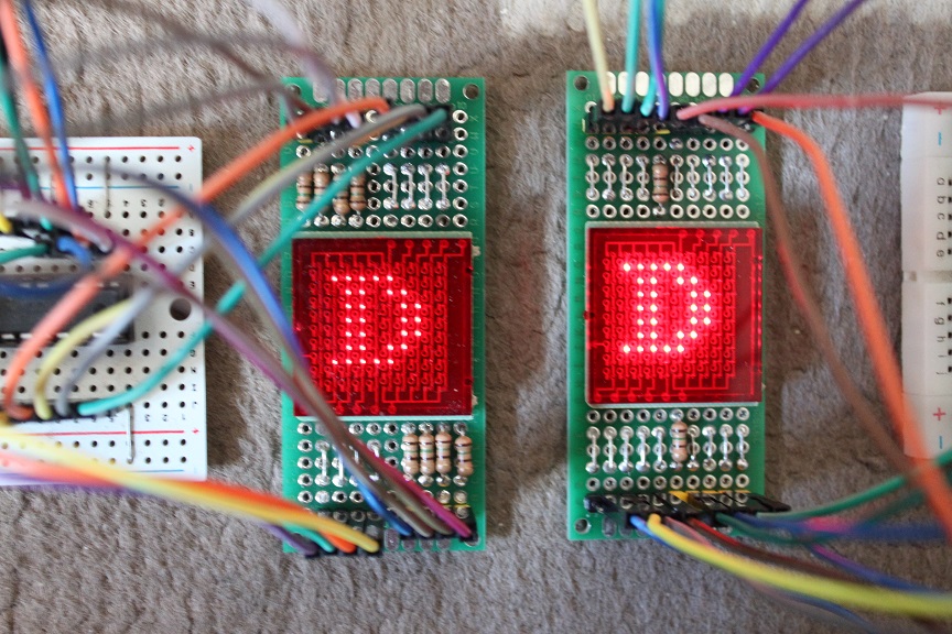
MAX7219経由で8x8 Dot Matrix LEDに半角英数字を表示する
*/
#include "LedControl.h" //
https://github.com/sej7278/LedControl
#include "font8x8_basic.h" //
https://github.com/dhepper/font8x8
#define INTERVAL 300 // You can change
/*
Now we need a LedControl to work with.
***** These pin numbers will probably not work with
your hardware *****
GPIO16(D0) is connected to the DataIn
GPIO12(D6) is connected to the CLK
GPIO14(D5) is connected to LOAD
We have only a single MAX72XX.
*/
//LedControl lc=LedControl(12,11,10,1);
LedControl lc=LedControl(16,12,14,1);
static unsigned long lastMillis;
static unsigned long timeOut;
const char string[] = "ABCD";
//
//
http://nuneno.cocolog-nifty.com/blog/2016/07/48x8led-0f0f.html
から借用しました
//
// 任意サイズビットマップのドットON/OFF反転
// bmp: スクロール対象バッファ
// w: バッファの幅(ドット)
// h: バッファの高さ(ドット)
void revBitmap(uint8_t *bmp, uint16_t w, uint16_t h) {
uint16_t bl =
(w+7)>>3;
// 横バイト数
uint16_t
addr;
// データアドレス
uint8_t d;
addr=0;
for (uint8_t i=0; i <h; i++) {
for (uint8_t j=0; j <bl; j++) {
d =
~bmp[addr+j];
if (j+1 == bl &&
(w%8)!=0) {
d &=
0xff<<(8-(w%8));
}
bmp[addr+j]=d;
}
addr+=bl;
}
}
// 任意サイズのビットマップにドットをセット
void setDotAt(uint8_t* bmp, uint16_t w, uint16_t h,
int16_t x, int16_t y, uint8_t d) {
if (x < 0 || y < 0 || x >= w || y >= h)
return;
uint16_t bl =
(w+7)>>3;
// 横必要バイト数
uint16_t addr = bl*y +
(x>>3); // 書込みアドレス
if (d)
bmp[addr] |= 0x80>>(x%8);
else
bmp[addr] &= ~(0x80>>(x%8));
}
// 任意サイズビットマップの指定座標のドットを取得
// bmp: スクロール対象バッファ
// w: バッファの幅(ドット)
// h: バッファの高さ(ドット)
// x,y: 座標
uint8_t getdotBitmap(uint8_t *bmp, uint16_t w, uint16_t h,
int16_t x, int16_t y) {
if (x>=w || y>=h || x <0 || y <
0)
return 0;
uint16_t bl =
(w+7)>>3;
// 横バイト数
uint8_t d;
d = bmp[y*bl + (x/8)];
if (d & (0x80>>(x%8)))
return 1;
else
return 0;
}
// 任意サイズビットマップの回転
// bmp: スクロール対象バッファ
// w: バッファの幅(ドット)
// h: バッファの高さ(ドット)
// mode: B00 なし, B01 反時計90° B10 反時計180° B11
反時計270°
void rotateBitmap(uint8_t *bmp, uint16_t w, uint16_t h,
uint8_t mode) {
if (mode == B00 || w != h || mode > B11)
return;
uint16_t bl =
(w+7)>>3;
// 横バイト数
uint8_t tmpbmp[h*bl];
uint8_t d;
memset(tmpbmp,0,h*bl);
if (mode == B01) { // 反時計90°
for (int16_t x = 0; x < w; x++) {
for (int16_t y = 0; y <
h; y++) {
d = getdotBitmap(bmp,
w, h, x, y);
setDotAt(tmpbmp, w,
h, w-y-1, x, d);
}
}
} else if (mode == B10) { // 反時計180°
for (int16_t x = 0; x < w; x++) {
for (int16_t y = 0; y <
h; y++) {
d = getdotBitmap(bmp,
w, h, x, y);
setDotAt(tmpbmp, w,
h, w-x-1, h-y-1, d);
}
}
} else { // 反時計270°
for (int16_t x = 0; x < w; x++) {
for (int16_t y = 0; y <
h; y++) {
d = getdotBitmap(bmp,
w, h, x, y);
setDotAt(tmpbmp, w,
h, y, h-x-1,d);
}
}
}
memcpy(bmp,tmpbmp,h*bl);
}
void setup() {
Serial.begin(9600);
/*
The MAX72XX is in power-saving mode on
startup,
we have to do a wakeup call
*/
lc.shutdown(0,false);
/* Set the brightness to a medium values */
lc.setIntensity(0,8);
/* and clear the display */
lc.clearDisplay(0);
lastMillis = millis();
timeOut = millis() + INTERVAL;
}
void loop() {
uint8_t bitmap[8];
static int pos = 0;
uint8_t buf[2];
int stlen = strlen(string);
char ch = string[pos];
// Serial.print("ch=");
// Serial.println(ch,DEC);
memcpy(bitmap, font8x8_basic[ch], 8);
// revBitmap(bitmap, 8, 8); //ビットマップの反転
rotateBitmap(bitmap, 8, 8, B10);
//1行単位に表示
for(int i=0;i<8;i++) {
lc.setColumn(0,i,bitmap[i]);
}
//次の文字を処理するかどうかの判定
unsigned long now = millis();
if (now < lastMillis) timeOut = now + INTERVAL;
if (now > timeOut) {
lastMillis = now;
timeOut = now + INTERVAL;
pos++;
if (pos == stlen) pos = 0;
}
}
|