/*
max7219.c
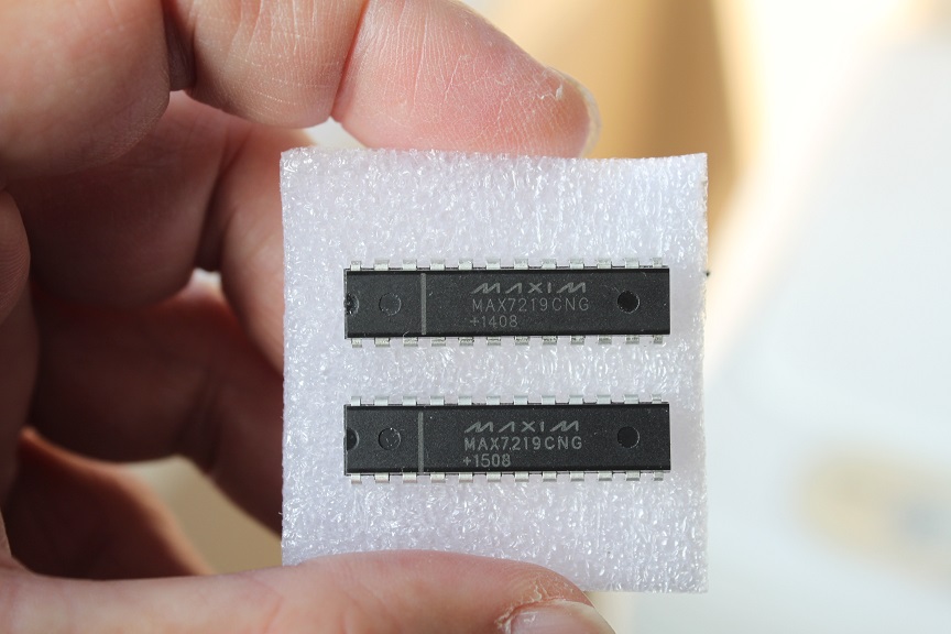
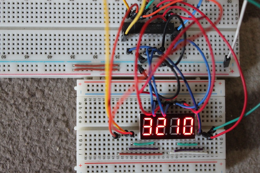
raspberry pi driving the max7219
to compile : cc max7219-2led.c -o max7219-2led
-lwiringpi
*/
#include <wiringPi.h>
#include <stdio.h>
#include <stdlib.h>
#include <stdint.h>
// define our pins :
#define DATA
0 // GPIO 17 header
pin 11
#define CLOCK
1 // GPIO 18 header
pin 12
#define LOAD
2 // GPIO 27 header
pin 13
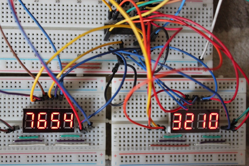
#define NLEDS
8 // Number of Digits
// the max7219 registers :
#define DECODE_MODE 0x09
#define INTENSITY 0x0a
#define SCAN_LIMIT 0x0b
#define SHUTDOWN 0x0c
#define DISPLAY_TEST 0x0f
void BitBanging (uint16_t output) {
uint8_t i;
for (i=16; i>0; i--)
{
uint16_t mask = 1 << (i - 1); //
calculate bitmask
digitalWrite(CLOCK, 0); // set
clock to 0
// Send one bit on the data pin
if (output & mask)
digitalWrite(DATA, 1);
else
digitalWrite(DATA, 0);
digitalWrite(CLOCK, 1); // set
clock to 1
}
}
// Take a reg numer and data and send to the max7219
//
// reg_number : Register Address of max7219 (0x00-0x0f See
datasheet)
// dataout : Send Data
//
void MAX7219Send (uint8_t reg_number, uint8_t dataout) {
int i;
digitalWrite(LOAD, 1); // set LOAD 1 to start
BitBanging((reg_number << 8) + dataout);
digitalWrite(LOAD, 0); // LOAD 0 to latch
digitalWrite(LOAD, 1); // set LOAD 1 to
finish
}
void displayNumber(int digit, uint32_t number) {
int i;
uint8_t data;
uint32_t num = number;
for(i=0;i<digit;i++) {
data = num % 10;
// printf("data[%d]=%d ",i,data);
MAX7219Send(i+1
,data); // displays the 1 digit
number
num = num / 10;
}
// printf("\n");
}
int main (void)
{
int i,j;
printf ("\n\nRaspberry Pi Max7219 Test using
WiringPi\n\n");
if (wiringPiSetup () == -1) exit (1) ;
//We need 3 output pins to control the Max7219:
Data, Clock and Load
pinMode(DATA, OUTPUT);
pinMode(CLOCK, OUTPUT);
pinMode(LOAD, OUTPUT);
MAX7219Send(SCAN_LIMIT, NLEDS-1);
/*
BCD decode mode off
data bits correspond to the segments (A-G and DP) of
the seven segment display.
BCD mode on
0 to 15 = 0 to 9, -, E, H, L, P, and ' '
*/
MAX7219Send(DECODE_MODE, 0xff); // Set BCD decode
mode on
MAX7219Send(DISPLAY_TEST, 0); // Disable test mode
MAX7219Send(SHUTDOWN, 1);
// come out of shutdown mode(turn on the digits)
for(i=0;i<NLEDS;i++) {
MAX7219Send(i+1, i);
}
for(i=0;i<5;i++){
MAX7219Send(INTENSITY, i); // set
brightness
sleep(1);
}
for(i=0;i<16;i++) {
for(j=0;j<NLEDS;j++) {
MAX7219Send(j+1,i); //
displays the 4 digit number
}
delay(500);
}
uint32_t number = 1;
for(i=0;i<NLEDS;i++) {
displayNumber(NLEDS, number);
number = number * 10 + (i+2);
//printf("number=%d\n",number);
delay(500);
}
return 0;
}
|